1.3 Complex Notation and Vector Diagrams
Current, voltage, and impedance relations across circuit elements can be represented by complex notation. This allows the addition and subtraction of various relationships between circuit elements to be calculated by vector algebra and vector diagrams in the complex plane. It provides a very nice visual form for presenting the magnitudes and phase relations of the RLC components. An arbitrary complex number can be represented by either of two forms:
1. Real (x) and imaginary (y) parts,
| x + iy | (1.3.1) |
where
i = ![]() ,
or
,
or
2. Magnitude (r) and phase (φ),
| x + iy = reiφ. | (1.3.2) |
Euler's formula, called "the most remarkable formula in mathematics" by Nobel prize winner Richard Feyman (1963), allows the graphical representation of these notations in polar, or vector, form in the complex plane. That is,
| ei φ = cos φ + i sin φ | (1.3.3) |
so
| rei φ = r cos φ + i r sin φ | (1.3.4) |
The graphical representation places the real part on the x axis (called the real axis) and the imaginary part on the y axis (called the imaginary axis). Such plots are called vector diagrams or Argand diagrams.
Therefore,
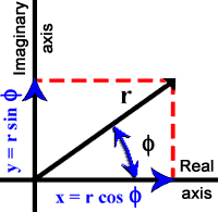 |
| Figure 1.5. Graphic representation of complex relations. |
The phase relations between r, y, and x are graphically illustrated in the Figure 1.5. For example, r leads x (= r cos φ) by φ radians ((φ/2π) 360°) and y (= r sin φ) leads x (= r cos φ) by π/2 radians (90°). This convention means that a quantity leading another is plotted counterclockwise (CCW) and one lagging is plotted clockwise (CW).