1.2 Series RLC Circuit
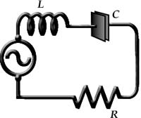 |
| Figure 1.2. Series RLC circuit. |
| I(t) = I0 sin ωt | (1.2.1) |
where ω = 2πf is angular frequency, f = 1/T is the harmonic frequency with period T. The instantaneous current through each circuit element is the same. This is referred to as being in-phase and since the current is in-phase in each circuit element, it is a good phase reference.
Series RLC Current-Voltage Relationships
Across the resistor, Ohm's law says that there is a linear relationship between current and voltage, VR, i.e.,
| VR = IR, | (1.2.2) |
where the resistance, R is the constant of linear proportionality.
Across the inductor, Faraday's law says that a voltage, VL, that is induced is proportional to the time rate of change of magnetic flux. This is expressed using the change in current flow, dI/dt as
| VL = L dI/dt, | (1.2.3) |
where the inductance, L is the constant of linear proportionality.
Across the capacitor, the voltage depends on the capacity to store electric charge. The ratio of the charge, q to the voltage (potential difference) across such a device defines capacitance, C such that
| VC = q/C. | (1.2.4) |
Applying Kirchhoff's voltage (second) law (the sum of the voltage drops in a closed loop equals the source voltage) yields
| V = VR + VL + VC | (1.2.5) |
or
| V = IR + L dI/dt + q/C. | (1.2.6) |
Using
| I = I0 sin ωt | (1.2.7) |
and recalling that the definition of current is
| I = dq/dt, | (1.2.8) |
we find after integration that
| q = -(I0/ω) cos ωt. | (1.2.9) |
Whereupon, after substitution into equation 1.2.6 above yields
| V = I0R sin ωt + I0ωL cos ωt - (I0/ωC) cos ωt. | (1.2.10) |
The quanities ωL and 1/(ωC) are the impedances of L and C which are called the inductive reactance, XL and capacitive reactance, XC , respectively. They clearly must have the units of ohms like R.
 |
| Figure 1.3. A oscilloscope can measure current and voltage time variations. |
| Figure 1.4. Temporal current and voltage relations across series RLC circuit elements. |